


|
Comments to the Measuring Circuit of Ring Generator 76 V
To construct this device is absolutely not the easiest devices to build. The device has got three mains transformers and a big glossing capacitor on 470 µF. All these things create problem about space and location. I placed the two small mains transformers at the upper location of the device box, the capacitor in the middle and the "2 X 115 V"-transformer at the lower location. This device is equipped with four mechanical switches which are marked by the symbols 'A', 'B', 'C' and 'D'. Page 7(8) The value 860 ohms at connection point 10 (C10) means: the input resistance is 860 ohms, which the network just before sees as a load of 860 ohms. I0 = 1,2 mA means: the unloaded current is 1.2 mA and that only concerns when there is no signal. The two output transistors MJE340 and MJE350 have each a heat sink. I recommend to locate these two heat sinks on the outside of device box. Page 8(8) The ring signal RS is shunted by a 47 kilo ohm resistor to ground. Across this resistor you're getting a mixed signal by the direct voltage of circa 50 volts and by the ring signal. The capacitor 4,7 µF 100 V, which is placed to the right, should prevent interferring signals to take place at the DC 340 V power supply. |
||||
|
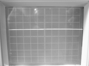
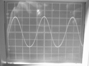
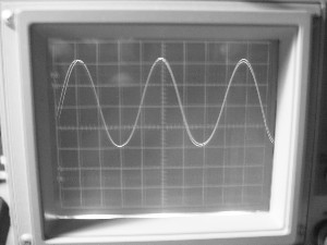
I've taken three pictures from my oscilloscope. The pictures below show three different output signals: (X-scale: 10 ms/square, Y-scale: 50 V/square) |
||||
|
|
|
||
|
|
||||
|
The Ring Generator shows a vacant phone line. |
The Ring Generator shows "Pure A.C.". |
The Ring Generator shows a vacant phone line with ring signal. |
||
|
T: picture 1, middle Phone line busy (A) T: picture 1, bottom Phone line busy Phone line free Relay from below: T: picture 2, left Type of ring signal (C) A ring signal switch (B) T: picture 4, right O U T |
||||
Back
Menu